65337ed57a

Leave Your Message

What Is the Best Optical Dividing Head in 2026

Choosing the best Optical Dividing Head in 2026 starts with the work it must perform. A machinist cutting evenly spaced slots needs dependable indexing. A metrology lab may care more about angular accuracy, repeatability, and documented calibration. These are different demands. The right choice depends on the job, not a polished product photograph.

Quality expert W. Edwards Deming is often associated with the reminder, “In God we trust; all others must bring data.” His words concern evidence, not dividing heads specifically, but the principle fits this purchase. Ask for accuracy specifications, calibration records, and repeatability data. Then check whether the head’s resolution matches your actual tolerance. A finely graduated scale can look impressive. It cannot, by itself, prove reliable performance.

Pay attention to practical details, too. Does the optical system provide a clear view under your shop lighting? Can the spindle be locked without shifting the setup? Is the mounting pattern compatible with your machine table? Imagine aligning a workpiece under a dim lamp, with coolant residue nearby. Small usability problems become real delays. Some specifications may still be hard to compare across brands; treat that uncertainty seriously. This guide will weigh accuracy, construction, compatibility, support, and price to identify strong options for 2026. The best choice is the one whose verified performance suits your work—and whose limitations you understand.
What Is the Best Optical Dividing Head in 2026

What an Optical Dividing Head Is and How It Works

An optical dividing head is a precision tool for positioning a workpiece at measured angles. It is commonly used for milling gears, slots, flutes, and equally spaced holes. The workpiece is secured on a spindle, while the spindle rotates through a controlled angular range.

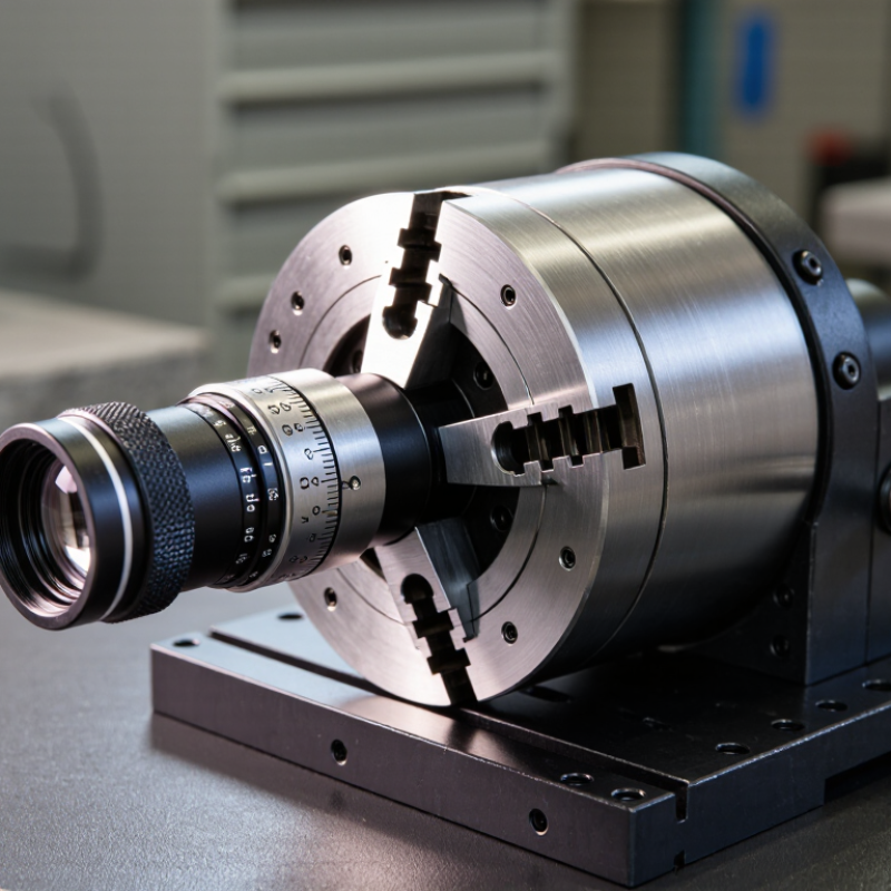
Its optical system uses a graduated glass scale, illumination, and a viewing lens or electronic reader. As the spindle turns, the operator observes scale markings and aligns them with a reference line. A locking mechanism then holds the selected position during cutting. Some designs use worm gearing for fine movement, while others support direct optical indexing. The best optical dividing head in 2026 should offer clear readings, low backlash, rigid construction, repeatable positioning, and reliable calibration records.

Small errors still matter. Dust on the optical path can blur a reading. Parallax may shift the apparent alignment. Thermal expansion can also change results during long machining cycles. It is not magic. In my workshop experience, careful clamping and a clean reference surface often improve accuracy more than a higher resolution scale. I would also check spindle runout, locking stiffness, and the condition of the illumination system before judging performance. A technically advanced head can still disappoint when setup habits are inconsistent. Calibration should be verified with a known angular standard, especially after transport or heavy use.


Main Types and Configurations of Optical Dividing Heads

What Is the Best Optical Dividing Head in 2026

Main Types and Configurations of Optical Dividing Heads

Choosing the best optical dividing head starts with its operating principle. A traditional optical head uses a glass circle, illuminated scale, and viewing microscope. It provides direct angular reading without relying on electronic feedback. This suits inspection, gear cutting, and manual indexing where visual control matters. Its weakness is obvious: reading errors increase when lighting, cleanliness, or operator eyesight changes.

Electronic optical heads use encoders and digital displays. They provide faster positioning and easier data recording. CNC-compatible configurations can connect with rotary tables, machining centers, and automated inspection systems. Horizontal models suit shafts, gears, and long workpieces. Vertical models provide better access to circular faces and drilling patterns. Some dual-axis configurations support complex angular machining, but setup becomes more demanding.

The International Federation of Robotics reported 541,302 industrial robot installations worldwide in 2023, a 10% annual increase. That trend supports demand for accurate, automation-ready dividing equipment. Still, automation does not automatically create accuracy. A 2024 machine-tool market analysis by Grand View Research indicates continued mid-single-digit growth through 2030, yet application differences remain important. A compact manual head may outperform a digital model during slow, careful inspection. I would question any selection based only on resolution. Backlash, spindle runout, clamping rigidity, and calibration records can matter more. Small errors become visible.

What Is the Best Optical Dividing Head in 2026?

Common angular indexing increments used with dividing heads. The required index count is calculated as 360° ÷ number of index positions.

Direct indexing is convenient for frequent standard divisions, while plate-based universal heads support a broader range of divisions. Optical readouts improve angular verification, and tilting or CNC configurations are better suited to compound or automated work.

Key Specifications for Evaluating Optical Dividing Heads in 2026

What Is the Best Optical Dividing Head in 2026

Key Specifications for Evaluating Optical Dividing Heads in 2026

Choosing the best optical dividing head starts with angular accuracy and repeatability. A practical unit should provide clear readings, stable indexing, and minimal backlash. Look for an optical scale with fine resolution, preferably measured in seconds of arc. Repeatability matters more than impressive resolution alone. During machining, a head returning to the same position prevents uneven tooth spacing and costly rework. Test it under load, not only on an empty bench.

Mechanical rigidity is equally important. A rigid spindle should resist vibration when cutting steel or hardened materials. Check the spindle bore, mounting interface, clamping method, and supported workpiece weight. A larger aperture may improve flexibility, but it can reduce compactness. Balance both needs. The optical system should remain readable under workshop lighting, dust, and coolant mist. That detail is easy to overlook.

Ease of calibration also separates dependable equipment from frustrating equipment. Ask whether zero adjustment, scale verification, and service procedures are clearly documented. Compatibility with digital readouts, rotary tables, and existing fixtures can save hours during installation. In my experience, smooth controls are valuable, especially during repeated manual setups. However, I would not trust a specification sheet alone. Actual test data may be incomplete. Check measured accuracy, temperature stability, and long-term wear records before buying. A small alignment error can become visible across a large circular pattern.

What Is the Best Optical Dividing Head in 2026? Key Specifications for Evaluating Optical Dividing Heads

Specification What to Check Why It Matters Evaluation Guidance
Angular readout and resolution Read the smallest graduation on the optical scale or circle, and check whether the instrument includes a vernier or other fine-reading feature. Resolution indicates the smallest displayed increment; it is not, by itself, a guarantee of measurement accuracy. Match the stated resolution to the angular tolerances of the work. Confirm how accuracy is specified and tested separately.
Angular accuracy Review the manufacturer’s stated angular error, its measurement conditions, and any calibration or inspection documentation. Accuracy describes how closely a measured or indexed angle corresponds to its true value. Compare specifications stated on the same basis, such as error per angle or over a defined rotation. Prefer traceable calibration records when required.
Indexing range and increments Check the available angular range, permitted indexing increments, and whether continuous positioning is possible. The indexing system determines which divisions can be set efficiently and repeatably. Verify that the required divisions can be produced directly or by an available indexing method; do not assume every head supports every division.
Spindle and workholding interface Confirm the spindle nose, center or taper arrangement, chuck or collet compatibility, and any supplied adapters. Interface compatibility affects setup time, workpiece support, and concentric mounting. Check drawings and dimensions against existing fixtures and the workpiece. Treat adapters as configuration-dependent unless included in the specification.
Workpiece capacity Review the stated center height, permissible workpiece dimensions, and load limits where provided. Capacity determines whether the head can safely support the intended part and tooling arrangement. Evaluate the complete setup, including workpiece overhang and cutting forces. Use the documented limits rather than appearance alone.
Spindle runout and bearing condition Look for documented spindle runout measurements and information about spindle support and maintenance. Runout can affect concentricity and the results of operations performed on a mounted part. Check the measurement method and test location. Compare like-for-like values and inspect used equipment for wear or damage.
Locking and clamping Assess the spindle lock, table or base clamps, adjustment controls, and access to locking levers. Secure locking helps prevent unintended movement during machining or measurement. Check that the head locks firmly without shifting the indicated position and that controls remain accessible on the intended machine.
Optical system and visibility Inspect scale contrast, illumination, viewing angle, magnification, and protection from dust or coolant. Clear, stable viewing reduces reading difficulty and helps operators use the instrument consistently. Assess visibility under actual workshop lighting and confirm whether illumination or protective accessories are included or optional.
Mounting and machine compatibility Check base dimensions, mounting slots or holes, machine-table fit, and clearance around the head. A compatible mounting arrangement supports a rigid setup and avoids interference with machine travel or tooling. Use dimensional drawings to verify fit, clamping access, and required operating clearance before purchase.
Calibration, documentation, and support Review the user manual, inspection records, calibration options, spare-part availability, and stated service procedures. Documentation and serviceability support reliable setup, maintenance, and long-term verification. For precision work, establish how calibration is performed and whether records are traceable to recognized measurement standards.
Overall selection decision Balance angular performance, workholding, capacity, mounting fit, visibility, and service requirements. The most suitable head depends on the application; no single specification determines performance for every job. Choose the unit whose documented capabilities meet the required tolerances and workflow, rather than selecting by resolution alone.

How Optical Dividing Heads Compare Across Different Applications

What Is the Best Optical Dividing Head in 2026

The best optical dividing head depends on the application, not a single specification. A manual milling job needs clear optical readings, smooth indexing, and dependable clamping. Small angular errors can become visible on gear teeth or fluted cutters. For these tasks, a rigid body and low backlash usually matter more than advanced automation.

CNC production creates different demands. Operators may value encoder feedback, repeatable positioning, and simple machine integration. Heavy workpieces also require strong support and stable locking pressure. In inspection work, fine graduations and consistent illumination are essential. A head that performs well during light cutting may struggle under vibration. That difference is easy to miss during a short demonstration. I have found that setup time also affects real productivity. A theoretically accurate head is less useful when alignment takes too long.

Tips: Match the head to the workpiece size, cutting force, and indexing frequency. Check angular repeatability with a calibrated indicator or reference plate. Test the locking mechanism after several adjustments. Record readings at different angles. Temperature can influence precision. Small details matter.

No head fits every application. That is the uncomfortable part. Reviewers should compare measured performance, maintenance needs, and operator skill requirements. A reliable choice should remain predictable after repeated setups, not only appear impressive when new.

How to Choose the Best Optical Dividing Head for Your Needs

What Is the Best Optical Dividing Head in 2026

How to Choose the Best Optical Dividing Head for Your Needs

Choosing the right optical dividing head starts with the work you actually do. For small, precise parts, check the spindle’s runout, angular scale readability, and locking stability. A clear glass scale helps you read divisions under workshop lighting without repeated adjustments. Match the unit’s capacity to your largest workpiece, including its fixtures. Oversizing can waste bench space; undersizing can limit future projects. Neither choice is ideal.

Consider how you will mount and align the head. A rigid base and accessible adjustment screws make setup less frustrating on a milling table. Check whether the optical system supports the division intervals you need, such as indexing common tooth counts or drilling evenly spaced holes. Verify this against the manufacturer’s specifications rather than assuming every head offers the same range. If possible, inspect a sample scale in person. Tiny markings can look sharp in a photograph and still be tiring to use.

Tips: Bring a typical workpiece or fixture when comparing models. Check scale visibility at your normal viewing angle, and test the locking mechanism for movement. Ask about calibration and service support. These details matter. I have seen buyers focus heavily on resolution, then overlook awkward mounting; that is an easy mistake, though workshop layouts differ. Keep a little room for the tool you may need later.